Differential Drive
Introduction
This project is going to cover how to make both a basic and an advanced differential drive.
Prerequisites
- Comfortable with all the goals and prerequisites of Java102.
- Comfortable with lambdas & functional interfaces
- Familiarity with types of sensors
- WPILib installed
Goals
Some understanding of and familiarity with:
- Robot code
- Simulation
- Testing robot code
- Control theory
- Command-based programming
Also, a working, simulated, tested differential drive!
What is a differential drive?
A differential drive is a type of robot drivetrain where two separately-driven groups of wheels are used to move the robot. By varying the speed of each wheel, the robot can move forward, backward, or turn. This setup is widely used due to its simplicity and high degree of control over the robot’s movement.
To move the robot forward/backward, both wheels must move at the same speed in the same direction. To turn, the wheels must move at different speeds or in opposite directions.
Creating your project repo
The first step will be to create a repository for this project. We'll be using this base template for this project (and all other robot code projects in SciGuides). Follow the instructions in the README to create a new repository based on the template. Give your repository a descriptive name such as "Differential Drive Bot".
In the README of your new repository, link this guide.
Make sure to clone the project on your computer inside of your code folder!
Robot Code Structure
Robot code is structured using subsystems and commands within FRC's command-based framework. This architecture simplifies robot programming by breaking down complex tasks into smaller, manageable pieces.
All of your Subsystem classes must extend SubsystemBase. (Commands extend Command, but you won't really be writing full Command classes).
Running commands and enforcing the one-command-per-subsystem rule is managed by the CommandScheduler. Essentially, if you want to run a command, you tell the CommandScheduler, and then each time the code runs the CommandScheduler goes through all the Commands that it has been told to run, and runs them.
Please read the following sheets before moving forward:
Understanding the hardware
In order to program a robot, you first need to understand the physical hardware that you are working with, and particularly the electrical components.
For this guide, we’ll be using CANSparkMax motor controllers paired with NEO motors.
- CANSparkMax: A motor controller developed by REV Robotics designed specifically for controlling brushless motors like the NEO.
- NEO Motor: A brushless motor designed by REV Robotics.
Let's look at what a differential drivetrain might look like:
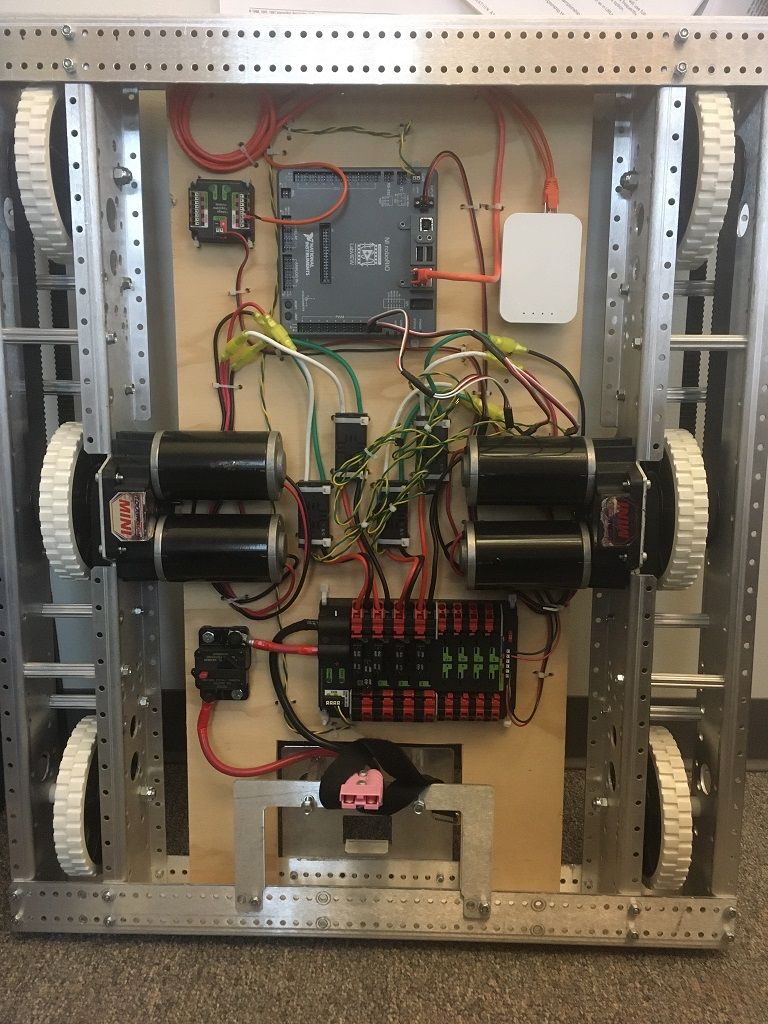
The black cylinders between the two center wheels are motors. As you can see, there there are two motors attached to each side of the drivetrain.
These motors are also connected via wires to motor controllers, which are connected ultimately to a roboRIO (gray square thing on the top). The roboRIO is a piece of hardware which connects and interfaces with all of the sensors and actuators on the robot (sensors collect data, actuators move). We can control those sensors and actuators by running code on the RIO.
- Remember
Ports.java? Well, in order to control our electronics and for the RIO to send them signals, we need to know what physical ports our components are connected to. That's what we mean when we say that this file stores the ports for our components.
The RoboRIO is connected to a radio (the white rectangle to the right of the RIO), which is how we generally connect our computers to the RIO.
Drive Folder
Our first step will be to create a drive folder for everything related to the Drive subsystem. It will include:
- a
Drive.javasubsystem that extendsSubsystemBaseand contains the logic to control the motors and the drivetrain. DriveConstants.java, containing whatever constants we will need for our subsystem (i.e. the dimensions of the drivetrain).
Once you do that, your files should look something like this:
Ports
In our Drive.java class, we will make all of our 4 motors using CANSparkMax objects. When you create a CANSparkMax object, you give it a port and a motor type (don't worry about what the motor type means for now). With that port, it is able to interface with the motor connected to the port through the RIO.
Before we create our motor objects, let's add our ports to Ports.java.
Currently, the file should look like this:
package robot;

public final class Ports {
  // TODO: Add and change all ports as needed.
  public static final class OI {
    public static final int OPERATOR = 0;
    public static final int DRIVER = 1;
  }
}
We structure our ports by creating a new static class within the Ports class for each subsystem (or in the case of OI, that's for the Xbox controllers). So create a new class for Drive ports!
package robot;

public final class Ports {
  // TODO: Add and change all ports as needed.
  public static final class OI {
    public static final int OPERATOR = 0;
    public static final int DRIVER = 1;
  }

  public static final class Drive {
    public static final int RIGHT_LEADER = 2;
    public static final int RIGHT_FOLLOWER = 3;
    // etc
  }
}
As we said earlier, there will be four motors total, two on the right and two on the left. We're going to call one on each side the leader, and one the follower.
In the example code I added ports for the motors on the right. Make sure you add for the ones on the left as well! You can assign any values that you want, as long as they are all different (and if you ever want to test this on a real drive train, you'll need to make sure the ports are accurate).
Drive Subsystem
Now let's go back to Drive.java and write our subsystem!
Motor instantiation
First off, we have to actually make our motor objects. We'll use the ports form Ports.java, and the motor type for all of our motors will be MotorType.kBrushless.
To do this, you will first need to import MotorType, Ports, and CanSparkMax. You will also have to import SubsystemBase so that you can make Drive into a Subsystem:
package robot.drive;

import com.revrobotics.CANSparkMax;
import com.revrobotics.CANSparkLowLevel.MotorType;

import edu.wpi.first.wpilibj2.command.SubsystemBase;
import robot.Ports;

public class Drive extends SubsystemBase {

}
We gave you all the imports for this, but in the future, a trick you can use is to start writing the thing you need to import and then press tab. So, in this case, if you were to start writing Drive extends SubsystemBase, but didn't finish the last word, SubsystemBase would come up as a suggestion:
 If you then press tab, it will finish the word for you and actually import SubsystemBase!
Okay, now we're ready to make our motors:
public class Drive extends SubsystemBase {
  private final CANSparkMax leftLeader = new CANSparkMax(Ports.Drive.LEFT_LEADER, MotorType.kBrushless);
}
Below the instantiation of leftLeader, make variables for all the other motors! (leftFollower, rightLeader, and rightFollower).
Motor configuration
For our motors to work the way we want them to, we'll need to configure some specific settings. This will happen inside of our constructor, and we will be using various methods of the CANSparkMax class.
The first thing that we'll do is reset all our sparks to a default state, clearing any old configurations that they may have had:
  public Drive() {
    for (CANSparkMax spark : List.of(leftLeader, leftFollower, rightLeader, rightFollower)) {
        spark.restoreFactoryDefaults();
    }
  }
Note: you'll need to import List for this
Next, we're going to set something called the idle mode of our motors, which essentially determines the behavior of the motor when it's not being told to do anything. The options are:
kBrake: stop as fast as possiblekCoast: don't provide any voltage and just let it spin freely
For a drivetrain, we don't want our robot to just keep drifting when we stop driving, so we want all our motors on brake mode (make sure you import CANSparkBase.IdleMode):
  public Drive() {
    for (CANSparkMax spark : List.of(leftLeader, leftFollower, rightLeader, rightFollower)) {
        spark.restoreFactoryDefaults();
        spark.setIdleMode(IdleMode.kBrake);
    }
  }
For the next part, we're going to need to understand why we're calling our motors leaders and followers. If you think about it, for a differential drive to work all of the wheels on one side need to be moving at the same speed. The point of having two motors isn't actually to control two wheels separately. Instead, it's to have enough power to control two wheels together.
So that means that we always want the two motors on the right and the two motors on the left to be moving the same way. We accomplish this by telling one motor on each side (the follower) to follow the other one (the leader). That way we only have to control the two leaders, and the followers will just copy them. We can do this using the follow method that of the CANSparkMax class.
  public Drive() {
      for (CANSparkMax spark : List.of(leftLeader, leftFollower, rightLeader, rightFollower)) {
        spark.restoreFactoryDefaults();
        spark.setIdleMode(IdleMode.kBrake);
    }

    rightFollower.follow(rightLeader);
    leftFollower.follow(leftLeader);
  }
Now, for our last setting, take a look back at the image of the drivetrain where you can see all of the electronics. Notice how the motors on the left are facing left, and the motors on the right are facing right.
By default, applying a positive voltage to the motors will make them go counterclockwise. So let's say that we want the robot to move straight, and so we apply the same positive voltage to both sides, and all of the motors move counterclockwise. Try to visualize what would happen.
Because the wheels are facing opposite directions, clockwise doesn't mean the same thing for the two sides. The left wheels will end up going backwards, and the right ones will go forwards, and instead of going straight, the whole drivetrain will rotate counterclockwise.
That's pretty confusing. Ideally, we'd like positive to mean forward for both sides. So in the code, we invert the left side. This means that it will negate every value we give it, so if we give it a positive voltage it will actually rotate counterclockwise. We do this using the setInverted method.
  public Drive() {
      for (CANSparkMax spark : List.of(leftLeader, leftFollower, rightLeader, rightFollower)) {
        spark.restoreFactoryDefaults();
        spark.setIdleMode(IdleMode.kBrake);
    }

    rightFollower.follow(rightLeader);
    leftFollower.follow(leftLeader);

    leftLeader.setInverted(true);
  }
Drive method
Now that our motors are configured, we can actually make a drive method that will allow the motors to run! This method will take in a leftSpeed and a rightSpeed which we will pass to our motors.
Side note: calling these values speed is actually a misnomer, since they specify both speed and direction, but using the terms interchangeably is pretty standard practice in this context.
We will be using the set method of the CANSparkMax class, which takes a number between -1 and 1, where 1 is full speed forwards, 0 is no speed, and -1 is full speed backwards. So we're actually giving percentages of our max speed, not the speed itself.
  private void drive(double leftSpeed, double rightSpeed) {
    leftLeader.set(leftSpeed);
    rightLeader.set(rightSpeed);
  }
Drive Command Factory
You might notice that the drive method above is private. But that means that we can't actually tell our robot to drive from Robot.java! So, why isn't it public? Well, when we tell subsystems to move, we generally always want that to be done through a Command, that way we can enforce the one-command-per-subsystem rule. So we actually don't want anybody outside of Drive to be directly calling this drive method.
Instead, we're going to write a command factory, which is just a fancy way of saying a method that returns a command. What specifically do we want our command to do? Well, our primary method of driving will be using inputs from a controller. We have an Xbox controller in Robot.java called driver, and the leftSpeed and rightSpeed values are actually going to be the y values of the left and right joysticks on that controller.
So our drive method should return a Command that drives the robot based on inputs from a controller. Since the controller is in Robot.java, not Drive (it is not part of the Drive subsystem), our method will need to take as inputs some way of retrieving the values from the controller.
Specifically, we're going to take two DoubleSuppliers, one for the left velocity and one for the right velocity. In Robot.java, we'll call our method and give it methods to get the left and right y values on the Xbox controller. So, here's our method header:
public Command drive(DoubleSupplier vLeft, DoubleSupplier vRight);
Note: the two drive methods have the same name, but are not the same method. As long as the types of the parameters are different, you can have multiple methods with the same name.
Next up, let's decide what type of Command we want to use. This isn't just something we want to do once - we need to get new inputs from the controller each tick - so we'll use a run command. We've talked about Commands.run, but in a Subsystem there's actually another method just called run, which calls Commands.run but uses that subsystem as the requirement. So drive.run(action) is the same as Commands.run(action, drive). That's the method we're going to use for this, since we want to create a RunCommand that requires a drive subsystem.
And the action is just going to be calling the other drive method using vLeft and vRight!
  public Command drive(DoubleSupplier vLeft, DoubleSupplier vRight) {
    return run(() -> drive(vLeft.getAsDouble(), vRight.getAsDouble()));
  }
Driving with the controller
Now we're going to go to Robot.java and write the code to actually drive the robot using the driver controller!
There should already be two CommandXboxController objects called operator and driver defined at the top of the class. You can ignore the operator controller, and we'll use the driver one for driving.
Next up, we need to actually create our instance of the drive subsystem! You can do this right under the comment that says // SUBSYSTEMS:
Drive drive = new Drive();
Now that we have our drivetrain initialized, we can set up driving with controllers. We're going to do that by setting a default command for drive. A default command is a command that runs on a subsystem whenever no other commands that require that subsystem are running. For drive, if we're not telling it to do something else, we always want it to be listening to the controller and driving.
We set a subsystem's default command using subsystem.setDefaultCommand(command). And we do those configurations in the configureBindings method inside of Robot. This method (along with configureGameBehavior) is called by Robot's constructor, and are used to configure settings that need to be configured right when the robot is started up.
  private void configureBindings() {
    drive.setDefaultCommand(drive.drive(driver::getLeftY, driver::getRightY));
}
Now, if you had a real robot to test on, it would drive!! But knowing that would probably be more exciting if you could see and drive around some sort of simulation. Unfortunately, we can't do that yet because to simulate the movement of the robot, we would need an estimate for where the robot is on the field, which we don't have yet. So let's work on getting that.
Odometry
Odometry is the process of using data from sensors to estimate your position and how it changes. In this case, the sensors that we'll be relying on are encoders (for our wheels) to and a gyroscope.
Brush up on the sensors guide if you're uncertain what encoders and gyros are.
Adding encoders
Our first step is to add encoders to our Drive subsystem. We'll be using the relative encoders that are built-in to our sparks. We can get them using the getEncoder method of CANSparkMax.
You can add the encoders right under where the sparks themselves are declared. Note that we only need the encoders of the leaders, because the followers should be doing the same thing as the leaders!
  private final RelativeEncoder leftEncoder = leftLeader.getEncoder();
  private final RelativeEncoder rightEncoder = rightLeader.getEncoder();
Conversion factors
By default, the encoders measure rotations of the motors. But we want to measure distance traveled. There are a couple of conversions that we need to make to do that:
- From rotations of the motor to rotations of the wheel
- This is dependent on the gears that connect the motor to the wheel.
- From rotations of the wheel to distance traveled
- This is dependent on the radius of the wheels. One rotation of the wheel translates to traveling one circumference of the wheel.
So to convert between encoder readings, we need to know the gearing (wheel rotations per motor rotation) and circumference of the wheels. We can put these values in the DriveConstants.java file. We'll choose some arbitrary values, but if you're testing on a real robot make sure these values are accurate.
package robot.drive;

public class DriveConstants {
  public static final double WHEEL_RADIUS = 0.08; //Meters
  public static final double CIRCUMFERENCE = 2.0 * Math.PI * WHEEL_RADIUS;
  public static final double GEARING = 8.0;
}
Then, from these values we can calculate our conversion factor for position. This is the number that we multiply the encoder rotations by to get distance traveled. We need to multiply by gearing to convert to wheel rotations, and then by circumference to convert to distance.
public static final double POSITION_FACTOR = CIRCUMFERENCE * GEARING;
We also need to calculate a separate conversion factor for velocity. The encoder by default gives you velocity in rotations per minute. We want it in meters per second. We can use the POSITION_FACTOR to convert to meters, and divide by 60 to convert from minutes to seconds.
public static final double VELOCITY_FACTOR = POSITION_FACTOR / 60.0;
Now we just need to use the conversion method from the encoder class inside the constructor of Drive.java.
    leftEncoder.setPositionConversionFactor(DriveConstants.POSITION_FACTOR);
    rightEncoder.setPositionConversionFactor(DriveConstants.POSITION_FACTOR);

    leftEncoder.setVelocityConversionFactor(DriveConstants.VELOCITY_FACTOR);
    rightEncoder.setVelocityConversionFactor(DriveConstants.VELOCITY_FACTOR);
Resetting the Encoders
At the start of the match (or any time you need to reset the robot's position), it's important to reset the encoder values to zero. This ensures that your distance calculations start from a known point.
We'll reset the encoders during the subsystem initialization (in the constructor):
    leftEncoder.setPosition(0);
    rightEncoder.setPosition(0);
Adding a gyroscope
We're going to use the AnalogGyro class. We need to give the port of the gyro to the constructor, so we need to add that port in Ports.java. Call the constant GYRO_CHANNEl and give it the value 1.
Let’s add the AnalogGyro to the top of the existing Drive.java file (under the encoders):
private final AnalogGyro gyro = new AnalogGyro(Ports.Drive.GYRO_CHANNEL);
Resetting the Gyro
At the start of the match, it's important to reset the gyro so that your heading starts at 0. We'll do that in the constructor of Drive.java.
gyro.reset();
You should reset the gyroscope anytime you need to ensure accurate heading data. Sudden robot movements, collisions, or physical rotation of the surface it is on can cause drift or skips over time, resulting in an incorrectly measured angle over the course of a match. Resets can correct for this.
Adding Odometry
Using the encoders and gyro we just made, we can start actually estimating our position. We do this using a WPILib class called DifferentialDriveOdometry, which helps estimate the position and angle on the field of a differential drive bot, using encoder and gyro values. Let's start by declaring a DifferentialDriveOdometry object at the top of our Drive subsystem.
private final DifferentialDriveOdometry odometry;
Initializing Odometry
We declared our odometry already, but we still need to initialize it. Odometry needs an initial orientation for the robot, so we're just going to assume that it starts at the origin with a heading of 0.
Read this for a brief explanation of Rotation2d, Translation2d, and Pose2d.
Here’s how we initialize the odometry in the constructor:
    odometry = new DifferentialDriveOdometry(
            new Rotation2d(),
            0,
            0,
            new Pose2d());
new Pose2d() just creates a Pose2d where all angles and coordinates as 0.
Updating odometry
To keep track of the robot’s position in real-time, we need to update the odometry regularly with the latest encoder readings.
Here's how you might update odometry:
  private void updateOdometry(Rotation2d rotation) {
    odometry.update(rotation, leftEncoder.getPosition(), rightEncoder.getPosition());
  }
Note: We are passing in rotation as a parameter because once we want to simulate our robot, it'll be easier to distinguish between our real and sim rotation.
Aside from updating our odometry, we might need to reset it. I will leave this up to you to figure out how to do. (Hint: odometry has a method called resetOdometry). We won't need it for this project but if you're using the drive for autos example, it is important to reset your odometry whenever autos start.
To ensure that our odometry is constantly updating as the robot moves, we run the updateOdometry() method periodically every tick (0.02 seconds by default). This will go in the periodic() method which all subsystems inherit from SubsystemBase, and is called every tick.
  @Override
  public void periodic() {
    updateOdometry(gyro.getRotation2d());
  }
Keep in mind, this will be changed in the simulation section to account for sim rotation.
Getting pose
The last thing to finish up our basic drive will be to get our pose based on the odometry. We can do this by using the getPoseMeters method from odometry. Keep in mind this returns a Pose2d. We want the robot's pose to be easily accessible by other classes, so we'll create a public method in Drive that returns the pose.
  public Pose2d pose() {
    return odometry.getPoseMeters();
  }
Control Theory
Before we get started, please make sure you have read the Control Theory reference sheet as we are going to assume you are aware of what PID and Feedforward generally do.
In this section, we're going to create PID and feedforward controllers to convert from desired speeds to voltages.
Why We Use Controllers
Before we dive into the code, let’s touch on why creating control systems are important for driving a robot. Ultimately, the motors run because they are given some voltage. Right now, we're driving using the motor.set method, which takes a speed. The CANSparkMax motor controllers have their own control systems that generate voltages based on speeds. But those systems aren't tuned to your robot. They work pretty well when you just have a free-spinning motor, but your motors are on robots. They're in gear boxes and are weighed down. So if you actually want to accurately reach your target speeds, you need to have control systems that are tuned to your system.
In this case, we're going to do that by making our own PID and feedforward controllers which we'll use to convert velocities to voltages, and then just feeding those voltages into our motors.
Feedforward
First off, we're going to create a feedforward model, which will use an ideal model of our system to tell us what voltages we should use. Its output will be our prediction of what voltage is required to maintain the velocity that we're trying to reach. This will be entirely based on our desired velocity, and will not take into account our current velocity at all. It factors in predictable challenges like friction, but not unexpected factors like slipping on the carpet.
Here's how we can create a feedforward controller:
private final SimpleMotorFeedforward feedforward = new SimpleMotorFeedforward(FF.kS, FF.kV);
- kS and kV are constants that become coefficients in an equation to convert from desired velocity to voltage
- The kS term in the equation accounts for constant voltage to overcome friction
- The kV term accounts for the voltage to maintain a certain velocity
- These FF constants are stored in
DriveConstants.javaand are imported. Keep in mind these are just random values to get you started with the project. With a real robot, it will be important to tune your values to work for your system.
  public static final class FF {
    public static final double kS = 1;
    public static final double kV = 3;
  }
PID
Next we can add a PID controllers. The feedforward model is pretty good, but it's not at all perfect. It also doesn't account for external forces that might get in the way of our movement. So we'll make PID controllers, which will actually take into account error (how far we are from the desired velocity). That way we can react when we aren't reaching our setpoints. Essentially, we're building on a pretty good estimate to account for its flaws.
With the feedforward controller we only made one. That's because all the FF controller needs is a velocity, and it will always return the same voltage when given the same velocity. So we can just use it twice, one for each side.
PID controllers on the other hand, don't just take into account your current speed and your current setpoint --- it also stores and uses your previous velocities. And our left and right motors have different velocities, so we need two controllers. One will be for the left wheels, and will store past velocity values for the left side, and one will do the same for the right wheels.
  private final PIDController leftPIDController =
      new PIDController(PID.kP, PID.kI, PID.kD);
  private final PIDController rightPIDController =
      new PIDController(PID.kP, PID.kI, PID.kD);
As you can see, we used three constants for this controller: kP, kI, and kD. We'll define them in DriveConstants.java.
  public static final class PID {
    public static final double kP = 8.5;
    public static final double kI = 0.0;
    public static final double kD = 0.0;
  }
Combining FF and PID
Now, let’s see how we can use these two control mechanisms to actually drive our robot! We’ll look at the drive method, which is responsible for controlling the motor voltages.
Based on our desired speeds, we can get outputs from PID and FF. We can then add these together and get our final voltage that we're going to send to the motor. To find these outputs, we need to give the controllers our desired speeds. The drive method really takes a percentage of our maximum velocity, from -1 to 1, rather than the actual velocity. So to find our desired velocities we can multiply leftSpeed and rightSpeed by our maximum speed.
We'll define our maximum speed in our DriveConstants class:
public static final double MAX_SPEED = 2; // Meters per second
Using that, we can find the feedforward and PID outputs for each side:
  public void drive(double leftSpeed, double rightSpeed) {
    final double realLeftSpeed = leftSpeed * DriveConstants.MAX_SPEED;
    final double realRightSpeed = rightSpeed * DriveConstants.MAX_SPEED;

    final double leftFeedforward = feedforward.calculate(realLeftSpeed);
    final double rightFeedforward = feedforward.calculate(realRightSpeed);

    final double leftPID =
      leftPIDController.calculate(leftEncoder.getVelocity(), realLeftSpeed);
    final double rightPID =
      rightPIDController.calculate(rightEncoder.getVelocity(), realRightSpeed);
  }
Finally, we combine the outputs and send them to the motors:
      double leftVoltage = leftPID + leftFeedforward;
      double rightVoltage = rightPID + rightFeedforward;

      leftLeader.setVoltage(leftVoltage);
      rightLeader.setVoltage(rightVoltage);
Simulation and Logging
Now we've reached the point where we can actually simulate our robot and drive it around! Please read the Simulation guide before continuing on with this.
Setting Up the Simulation
To simulate the drivetrain, we’re going to use the DifferentialDrivetrainSim class. This simulation will model the physical characteristics of our robot—like the motors, mass, and wheel dimensions—so we can see how the code will affect the robot in a virtual environment.
Here’s how we set it up in our Drive.java constructor:
  private final DifferentialDrivetrainSim driveSim;
  // ...
  public Drive() {
    // ...
    driveSim =
        new DifferentialDrivetrainSim(
            DCMotor.getMiniCIM(2),
            DriveConstants.GEARING,
            DriveConstants.MOI,
            DriveConstants.DRIVE_MASS,
            DriveConstants.WHEEL_RADIUS,
            DriveConstants.TRACK_WIDTH,
            DriveConstants.STD_DEVS);
    //...
  }
Remember that all of these values would be stored in DriveConstants.java:
  public static final double TRACK_WIDTH = 0.7112; // Meters
  public static final double WHEEL_RADIUS = 0.08; //Meters
  public static final double GEARING = 8.0;
  public static final double MOI = 7.5;
  public static final double DRIVE_MASS = 60.0; //kg
  public static final Matrix<N7, N1> STD_DEVS = VecBuilder.fill(0, 0, 0, 0, 0, 0, 0);
By setting up the simulation with these constants, we’re creating a physics model of our robot that behaves similarly to how it would in real life.
Before we start periodically updating our sim values, make sure to set the voltage to our sim drive in the drive method (the one that returns void):
driveSim.setInputs(leftVoltage, rightVoltage);
Next, we need to update our odometry using our simulated heading in simulation:
  public void periodic() {
    updateOdometry(Robot.isReal() ? gyro.getRotation2d() :
                                    driveSim.getHeading());
  }
Robot.isReal()returns whether or not we are connected to a real robot- What are the
?and:symbols? That whole statement is a ternary operator.
Simulation periodic
The simulationPeriodic method is where we update the simulation. This method is called every tick (0.2 seconds) when the robot is simulated so that we can keep the simulated sensors and drivetrain in sync with the rest of the code. The @Override annotation above the method is there so that the compiler knows it's the inherited method from SubsystemBase, but it isn't necessary to include.
  @Override
  public void simulationPeriodic() {
    // sim.update() tells the simulation how much time has passed
    driveSim.update(Constants.PERIOD.in(Seconds));
    leftEncoder.setPosition(driveSim.getLeftPositionMeters());
    rightEncoder.setPosition(driveSim.getRightPositionMeters());
  }
leftEncoder.setPositionandrightEncoder.setPositionupdate the simulated encoder positions to match the simulated robot’s movement.
This method ensures that our simulated sensors provide accurate feedback as the robot "moves" in the simulation, allowing us to test and tweak our code.
Logging: Capturing Important Data
Now let’s talk about logging. Logging, or telemetry, is a way of recording information in real time. That information might include data from sensors, estimated positions, what command is running, etc. Logging is crucial for understanding how our robot behaves over time, diagnosing issues, and improving performance. Read the Telemetry doc to learn more about logging and how we do it!
We’re going to use a tool called Monologue for logging, which gives us a structured way to record and analyze data from the robot’s systems. This should already be set up in the configureGameBehavior method in Robot.java. You should see the following lines:
    Monologue.setupMonologue(this, "/Robot", false, true);
    addPeriodic(Monologue::updateAll, kDefaultPeriod);
    addPeriodic(FaultLogger::update, 1);
This initializes Monologue with our robot, setting up the logging system to capture data as the robot runs and makes sure Monologue logs data at regular intervals, which we’ve defined with kDefaultPeriod. By logging data regularly, we can view information in real time and later review how the robot performed and make informed adjustments to our code.
Using Monologue for NetworkTables Logging
We use NetworkTables (NT) to make logging specific variables or objects easier. You should log any values that might be useful for debugging, or that will help you understand what is happening with the robot in general. So that includes commands, joystick inputs, voltages, positions, etc..
We use the @Log.NT annotation to indicate what values we want to be logged, and Monologue will periodically capture and record those values, which we can view in realtime or afterwords on dashboards like Shuffleboard or SmartDashboard.
Let's get started by making a Field2d object (discussed in the Simulation reference sheet):
  @Log.NT
  private final Field2d field2d = new Field2d();
Updating the Robot: periodic
The field2d will show us a field, but we want to actually see our robot moving on the field, so we need to periodically update the Field2d object with the position of our robot. We'll do that in the periodic method because we want our position to be updated regularly, and whether or not our robot is simulated.
field2d.setRobotPose(pose());
Seeing the result
Start by launching sim and opening up NetworkTables. Use the sim gui guide to help you navigate around.
To see our Field2d widget, go to NetworkTables, then SmartDashboard, and click "field".
Next, to see our logged data, click NetworkTables and the first option. You should see something similar to the image below.
Since our driver port is 1, make sure your joystick is also on the same port value in sim or else it will not get any inputs.
Lastly, to control the differential drive properly, the joystick will require to have 6 total axis as shown below. You can add more and change the bindings by going to DS then clicking on the settings of which ever keyboard you are using.
Unit Testing & System Checks
Coming soon!